|
|

|
| Γνήσια αξεσουάρ & ανταλλακτικά κινητής τηλεφωνίας! | |

  |
Special offers!

Delivery with BOXNOW Contact with us for more information (UNTIL 60X45X17CM) MEDIUM
Delivery with BOXNOW Contact with us for more information (UNTIL 60X45X17CM) MEDIUM DELIVERY-BOXNOW (SIZE: 60X45X17CM) MEDIUM3,23€+VAT  4,01€ 4,01€ 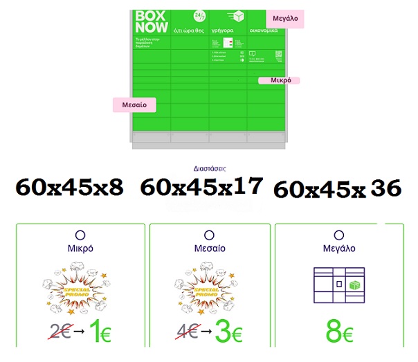
Delivery with BOXNOW contact with us 2109566401 (until 60X45X36CM) BIG
Delivery with BOXNOW contact with us 2109566401 (until 60X45X36CM) BIG DIMENSION DELIVERY-BOXNOW (SIZE: 60X45X36CM) BIG6,45€+VAT 8,00€ 
Delivery with BOXNOW contact with us 2109566401 (until 60X45X08CM) SMALL
Delivery with BOXNOW contact with us 2109566401 (until 60X45X17CM) SMALL DELIVERY-BOXNOW (SIZE: 60X45X8CM) SMALL1,61€+VAT 2,00€
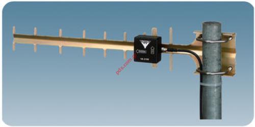
Antenna base Yagi Procom for UMTS 2100MHZ (10db)
ORDERING DESIGNATIONS TYPE PRODUCT NO. YA 2100 130001553 Top of page SPECIFICATIONS ELECTRICAL MODEL YA 2100 ANTENNA TYPE 9-element Yagi-antenna FREQUENCY 1900 – 2200 MHz IMPEDANCE Nom. 50 Ω POLARIZATION Linear (vertical or horizontal dep. on orientation) GAIN 10 dBi 8 dBd FRONT-TO-BACK-RATIO ≥ 15 dB HALF-POWER BEAMWIDTH Approx. 35° (E-plane) Approx. 45° (H-plane) BANDWIDTH 200 MHz SWR ≤ 1.8 @ 1.9 - 2.2 GHz MAX. POWER 25 W MECHANICAL MATERIALS Antenna: Gold aludine, Aluminium Fittings: Stainless steel COLOUR Aludine “gold” TOTAL LENGTH 570 mm MAX. ELEMENT HEIGHT 100 mm WEIGHT 300 g (incl. bolts) CONNECTORS FME-connector (cable to be ordered separately) MOUNTING On 30 – 50 mm dia. mast tube TYPICAL SWR AND GAIN CURVES SWR ¯ ¯ ¯ Gain dBi ¯¯¯¯¯¯¯ f. MHz With the YA 2100 you will experience a significant improvement of the quality of your communication on the 2100 MHz networks. INSTALLATION STEPS Mount the antenna on a 30-50 mm diameter mast tube using the accompanying fittings and bolts (see illustration overleaf). The antenna is to be oriented as indicated on the connection box of the antenna. Direct the antenna towards the nearest base station for the 2100 MHz network in question. The correct direction may be determined using the field strength indicator telephone: Mount the antenna on your mast. Rotate the antenna (in the horizontal plane) while observing the field strength indicator. Choose the direction in which the highest field strength level is observed and fasten the antenna. Top of page TYPICAL RADIATION PATTERN (E-PLANE) TYPICAL RADIATION PATTERN (H-PLANE) |
Quick product search
|


Members login |
Newsletter |
| Terms of use | Shipping and returns | |